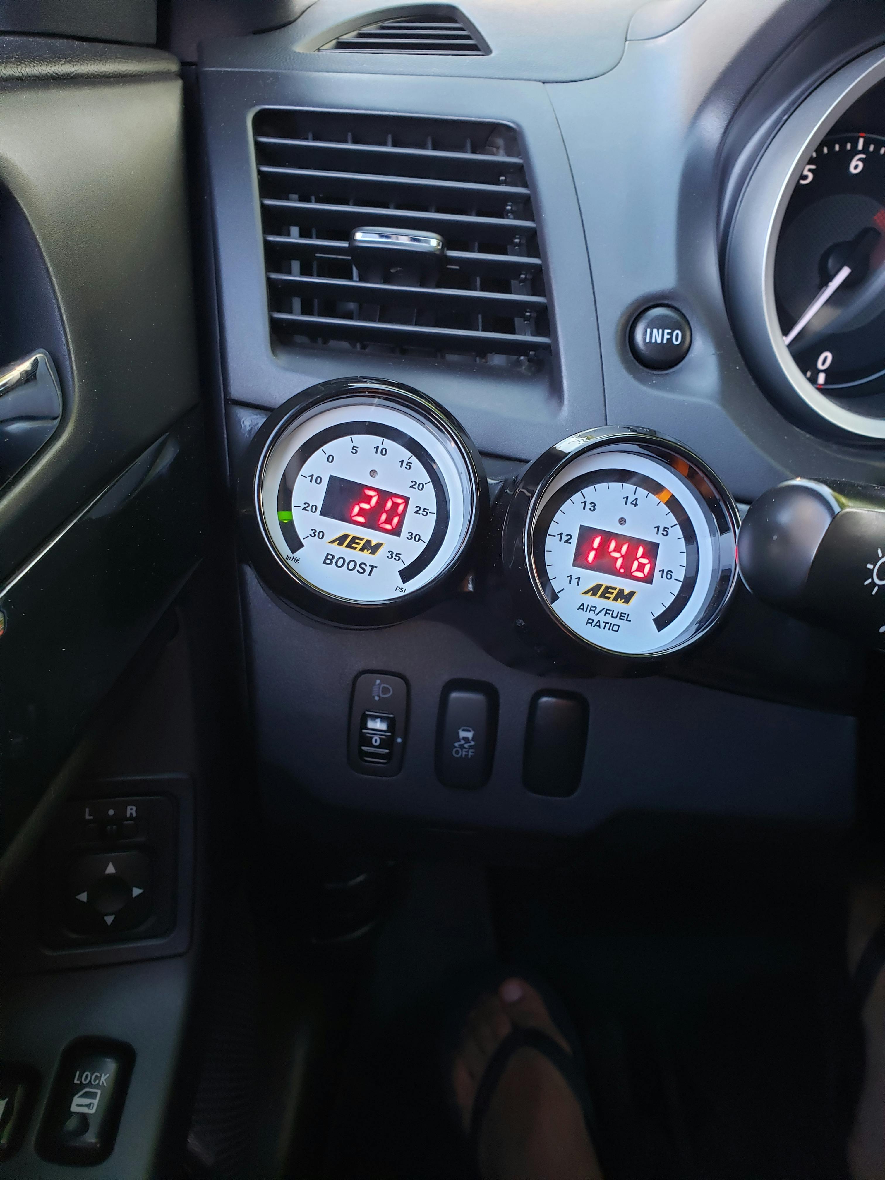
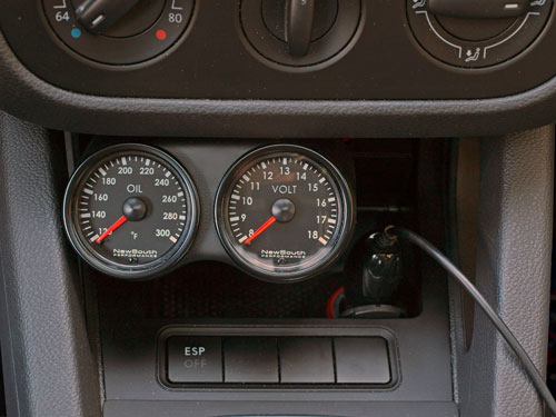
Tools Needed:
- Defi hardware
- 42Design 1/8NPT adapter
- Teflon tape
- Electrical tape
- Jack & Stands
- Small Flashlight
- Phillips and Flathead
- 4' & 8' black UV zip ties
- Snips or scissors
- 8mm HEX key & pry bar
- 10mm wrench
- 17mm wrench
- 11/16 wrench
- 3/8 drill
Glovebox:
Use the Glovebox Removal directions for illustrations on how to remove the glovebox. (http://www.evolution-8.com/howto/glovebox.php)
Grommet:
In the passenger corner side of the engine bay you will see a black grommet that leads into the cab. This is just behind the glovebox. Push the grommet from the engine bay into the cab. You may want to put piece of paper on the inside of the cab, just below the grommet, to deflect it towards the cab so you do not loose it once it is pushed through.
Â* Â*
Use a 3/8 drill bit to tap a whole into the grommet. A 3/8 inch hole will allow enough room for 2 defi sensor wires to fit with a little play.
Boost Pressure Sensor:
Find the black w/ blue striped vacuum tube located to the left of the throttle body, on the passenger side, and disconnect it. Cut a short piece off of the Defi supplied vacuum hose, connect it the engine and the other end to the center port on the T adapter. Next connect the OEM vacuum tube to one side of the T and the Defi hose to the other. You may want to trim some excess length from the OEM and Defi tubes. Attach the Defi Boost Sensor to the 10mm bolt location illustrated below. Connect the vacuum hose to the sensor and run the Defi electrical connection from the sensor to the glove box grommet hole and into the cab for the Control Unit II installation. Use the 4' zip ties on each vacuum connection and snip any zip tie tails.
Â* Â*
Oil Pressure/Temp Sensor:
Loosen the lugs on the front passenger wheel, jack the front of the car up and place it on blocks. Remove the front passenger wheel. Use a flathead screwdriver to remove the 4 pull clips and then remove the oil filter wheel well cover.
Just above the oil filter is an 8mm HEX bolt that will be removed to attach the oil pressure/temp sensor. There is a second location, lower on the oil filter housing, that can be used but the upper connection is usually preferred. You can attach a pressure sensor to one and a temp sensor to the other. You will need to remove the oil filter to access the lower 8mm bolt location but it is not necessary with the upper location.
Use the 8mm HEX key and attach a pole or pry bar for leverage as these bolts are on REALLY TIGHT. Break the 8mm bolt loose but leave it in place. A 1/8NPT reducer is needed to attach sensors to these locations. The 42Design 1/8NPT adapter is suggested. If you will be using the lower oil bolt location, you may need to use the 45 degree angle connection which comes with the 42Design reducer, otherwise; you can use the oil bolt location above the oil filter which does not require the angle adapter. Apply teflon tape to the sensor threads and screw it into the reducer using a 11/16 and 17mm wrench. Apply teflon tape to the reducer. Remove the now loosened 8mm bolt and quickly insert the reducer and tighten it with a 11/16 size wrench. This method will limit the loss of oil.
Attach the Defi electrical connection to the sensor. Use the 8' zip ties to run your wires into the glove box grommet hole then into the cab for the Control Unit II install. You will notice electrical tape on the end of my sensor which I attached for additional weather protection.
Defi Control Unit II:
Use a 10mm wrench to remove the negative connection on your battery. Use the Stereo Surround directions for removing the stereo from your dash. Run the CUII electrical connection wire behind the dash and up through the stereo opening. Use the Defi supplied wire taps to splice into the radio wiring harness using the following color combinations.
Control Unit II Radio Harness
Red - Â* Â*Red w/ Black Stipe
Orange -Â* Blue w/ Yellow Stripe
White - Â* Green w/ White Strip
Black - Â* Â*Bolt near radio
I prefer mounting the CUII under the center cubby. You can try to use the included double sided tape but I had troubles with it staying on so I used epoxy. You can still remove the cubby, even with the CUII attached. Remove the 2 phillips screws located under the cubby opening and pull it towards the cab. Being that the center cubby is detachable, this will allow for easier connections to the back of the CUII. Run the sensor cable connections behind the dash and to the appropriately labeled connection on the CUII. If you are using more than one sensor, use 4' zip ties to keep the sensor wires together. Use 8' zip ties to attach the sensor wires to different areas under the dash.
Â* Â*
Defi Gauges:
The Defi Link and Defi BF gauges allow you to chain the gauges together so that only a single wire needs to run from the CUII to your gauge mounting locations. The back of each gauge has 2 connections and it does not matter which one is used to daisy chain or for the master run back to the CUII. If you are using the BF gauges you will need to attach your gauge wire to meter port B. If you are using Defi Link gauges, you will attach your gauge wire to meter port A. You cannot mix Defi Link and Defi BF gauge types together.
Â* Â*
Re-attach the negative terminal of your battery and turn your car on to check that your gauges start up. Run the car for a while to insure there are no oil leaks from the oil sensors before re-attaching the wheel and dropping your car. Hit the Warning button then the up and down buttons on the CUII to set the warning or alarm values on each gauge.
from: http://www.evolution-8.com/howto/defi.php#defi1
- Defi Boost Gauge Install Evo Xl
- Defi Boost Gauge Install Evo X
- Defi Boost Gauge Install Evo X1
- Evo X Defi Boost Gauge Install
Defi Boost Gauge Install Evo Xl

Your cart is currently empty. View cartCheckout Wish list Where's my stuff? Blow off Valve Brakes Clutch Engine Exhaust Fuel Supply Intercooler Maintenance Turbo Privacy statement | This installation covers the Defi Link EGT gauge and is identical for the Defi BF EGT. Installation is similar for all other EGT gauges except for the electrical connection to the gauge itself. Most brands that do not have a main 'head unit' for the gauges like Defi Link and BFs, will have a box that is connected between the probe and the gauge. As with the boost gauge, this install is geared towards installing the EGT probe. How and where the gauge is mounted is totally up to you... NOTE: The way we installed this EGT probe fitting does not require the exhaust manifold to be removed from the car. While installing EGT fittings this way has never been a problem for us in the past, it certainly isn't the absolute 'ideal' method either. Any metal shavings that run through your turbine housing could potentially be trouble for the turbo, so use this method at your own risk and follow the tips to keep it as clean as possible. If you have any concerns at all, the only absolutely safe method is to completely remove the manifold from the engine/turbo, drill and tap it and then clean it out well prior to reinstallation. Probably the biggest decision to make in this installation is where to mount the EGT probe. Ideally, the probe should be mounted in the exhaust manifold runner of the cylinder most likely to run the leanest. Based on our 4G63 experience, this would normally be cylinder #1 or #2 and, judging from plug readings, the Evo 4G63 is no different. The EGT probe can pretty much be tapped anywhere in the exhaust manifold that has room for it. Likewise, the probe can also be tapped directly in the O2 sensor housing or in the downpipe. Mounting the probe after the turbo (O2 housing or downpipe) has the benefit of not sending chunks of metal through your turbine housing should the probe ever break (or during the install), but the drawback is a lower, and some feel, more inaccurate reading. Readings can be anywhere from 100°-300°F lower than with the probe mounted in an exhaust manifold runner. Why? The turbine and O2 housings are very good heatsinks. For our install, we will be installing the probe in the #2 runner of the exhaust manifold.
|
Defi Boost Gauge Install Evo X

Defi Boost Gauge Install Evo X1

This installation covers the Defi Link EGT gauge and is identical for the Defi BF EGT. Installation is similar for all other EGT gauges except for the electrical connection to the gauge itself. Most brands that do not have a main 'head unit' for the gauges like Defi Link and BFs, will have a box that is connected between the probe and the gauge.
Evo X Defi Boost Gauge Install
Boost Gauge Install This write up covers the installation of a Defi Turbo gauge and will be similar for all electronic and mechanical boost gauges alike. Depending on the brand and gauge type (electronic/mechanical), the difference will be how the connection is made from the pressure source to the gauge itself. Defi boost gauge installed. I left out the housing. Looks much better. Boostin at 22-23:rock:.edited- check out post #41. Saved by William Campos. Defi meter BF oil pressure and exhuast temp sensor: Members Buy/Sell - EVO X (4B11) 0: Jul 26, 2015: S: WTS Amber Delfi Gauges, Water Temp, Oil Temp, Oil press w/C2: Members Buy/Sell - EVO 1-9 (4G63) 0: Jul 22, 2015: K: WTS Defi BF Gauges - Boost, Oil Temp, Oil Pressure: Members Buy/Sell - EVO X (4B11) 1: May 30, 2015: E: WTS defi boost. 2009-2015 Lancer RalliArt. See All Mitsubishi. 2007-2017 GT-R (R35). DEFI Racer N2 Boost Gauge (52mm, 30 InHG - 30 PSI, Red) $256.50.
